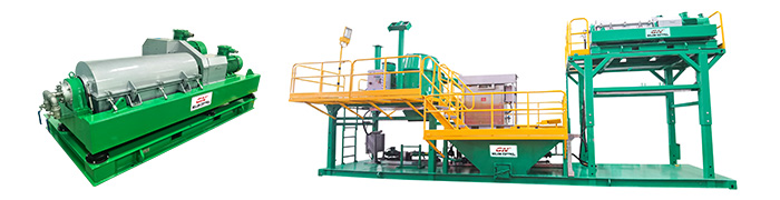
Dewatering decanter centrifuge, belt pressure filter is the 2 most normal equipment used for waste water treatment and sewage treatment. Below are some features of the 2treatment machines, to tell the different of them, and may help clients make decision.
Chemical consumption of Dewatering decanter centrifuge and belt pressure filter
Dewatering decanter centrifuge, as its centrifugal force is huge, it can remove ultra fine particles from sewage or waste water. The chemical enhancing rate is around 1.2kg/tds,the recovery rate of sewage is around 95%. Water content in the mud cake after dewatering is 65%~80%.
Belt pressure filter in order to improve treating capacity, the filter belt cannot be too much fine. To prevent ultra fine slurry passing the filter belt, more flocculent should be enhanced to get bigger size floc. The chemical enhancing rate is around 3kg/tds, the recovery rate of sewage is around 95%. water content in the mud cake after dewatering is around 80ï¼….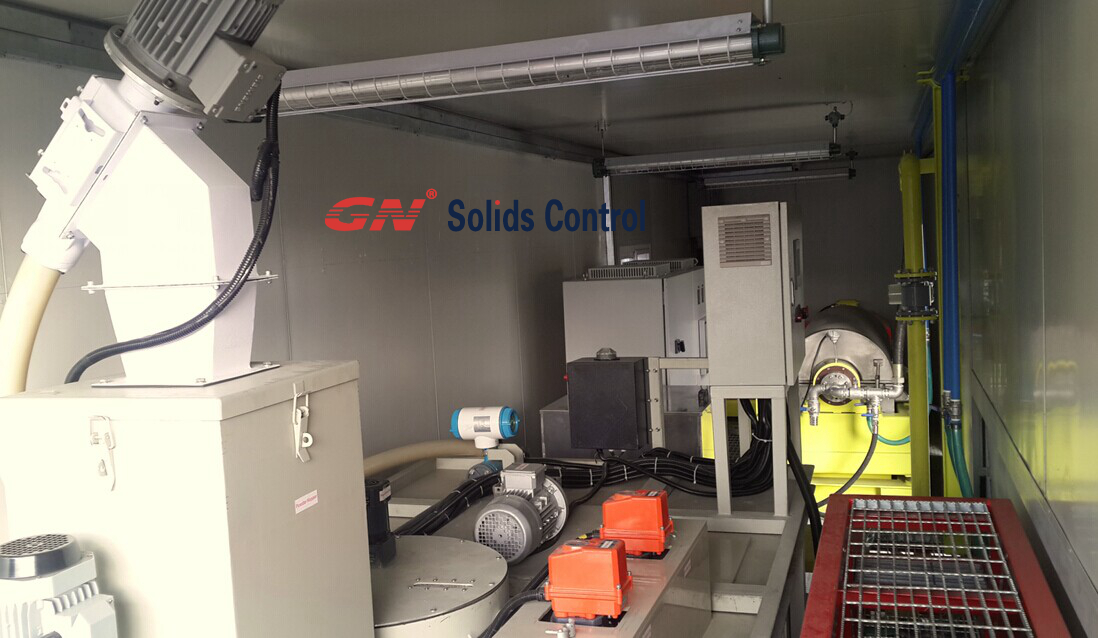
Compared with belt pressure filter, Decanter centrifuge utilize less chemicals. And in some applications, dewater centrifuge can get a good separation performance without adding in any chemicals. Belt pressure filter has to add chemicals for all materials.
Electric consumption and water consumption of Dewatering decanter centrifuge and belt pressure filter
Dewatering centrifuge has a higher electric consumption compared with pressure belt filter. But dewatering centrifuge does not need water for flushing during running. It only need to flush the inside bowl and propeller before stop running. Dewater centrifuge does not need much water for flush. Pressure belt filter should flush the whole filter belt for many times. The water for flush will come back to the system for recycling. It increases the handling load of the system.
Man power cost of dewatering centrifuge and pressure belt filter
Dewatering centrifuge is easy for operation. Especially from some leading suppliers, like GN Solids Control, there are PLC smart control for dewatering centrifuge. 1 operator can control 2 ~ 3 sets dewater centrifuge at the same time.
Pressure belt filter is complex for operation. It requests 1~2 operators for 1~2 pressure belt filter.
Based on above features, and the cost of each machine, clients can choose the suitable separation machine per his jobsite condition.
- Details
-
Published: 12 August 2016
GN Solids Control is an incorporated company for manufacturing often the drilling mud system as well as drilling waste management equipment and also system. Established in 3 years ago in China, GN has grown from a local China's company to an international corporation with its products sold to in excess of 60 countries. In 2014, GN set up its foreign subsidiaries in US and also Russia to get closer to the neighborhood customer and better provide the local market.
Among all typically the GN’s product line, there are presently there main ones which are more dependable, mature and popular already in the market, they are shale shaker, decanter centrifuge and cutting dryer. As one of the key components from the solid control and drilling waste management system, decanter centrifuge plays an important role within the solid and liquid separating process.

Among the Decanter centrifuge’s different specification and configuration settings, GNLW 363C is the most common and reliable, it is the movie star product. There are fixed velocity centrifuge and VFD manipulated centrifuge. There are many highlights regarding the equipment: the bowl materials is made from duplex stainless steel 2205 which is made by centrifugal sending your line, and it’s much better than metal 304 and stainless steel 316. The solid waste launch port is protected through special ceramic inserts that is certainly made by world famous manufacturer along with longer and more endurable lifetime. The adjustable effluent dock make the pond depth adjusting easier and more convenient and also fast. The pneumatic operated spring will make the beginning of the cover more easily and also safely. During the transportation, typically the bowl lifting bracket are able to do as the protection for the bearings. The bearings are made from the world famous SKF company. Both motors are placed at a single side of the equipment and prepare it smaller footprint. The actual conveyor surface is made from Tungsten carbide tiles which is much more endurable and easy for servicing. The VFD system is usually provided by ABB or SIEMENS. ATEX and IEC EX LOVER for zone 1 control panel can be provide seeing that request.
We will try our best to aid your business to be successful. Welcome to take a look at www.gnsolidsamerica.com and please send your current inquiries to USA@gnsolidscontrol. com
- Details
-
Published: 05 August 2016
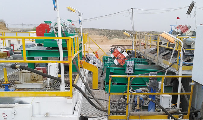
Decanter centrifuge and 3-phase centrifuge is widely used in a widely range of applications. As most clients may know, GN design and made decanter centrifuges are widely used in oil and gas drilling field, they can be used for dewater centrifuge, barite recovery centrifuge, fine solids separation centrifuge, waste water treatment centrifuge, oily sludge separation centrifuge, etc…
Below is the popular applications of GN existing centrifuges
1) TBM Mud Cleaning
2) Dredging Slurry Separation
3) Industry Waste Water Treatment.
4) Drilling rig mud Solids Control
5) Oily Sludge separation
6) Municipal Sewage Sludge Purification
7) Mining slurry Separation.
Here is a good new to all GN clients: GN Solids Control makes a huge invest on the research and developing of different industry application centrifuge. GN design and develop centrifuge per different separation demands of different industry. GN Solids Control will promote more new centrifuge models in the coming year.
Below are some of the new decanter centrifuge applications from GN Solids Control
1) Centrifuge for sludge dewatering, mud dewatering, and suspension treatment
2) Centrifuge for thickening sludge or mud. It is to reduce the solids percentage and make it suitable for Digestive tower treatment.
3) Centrifuge for clarifications of different types of liquid
4) 3- phase centrifuge to separate 3- phase mixtures, for example, two immiscible fluid phases with a kind of solid phase. It is popular used for oil water and mud separation to treat the oily sludge in oil and gas drilling field.
5) Centrifuge for clarifying solids in a wet suspension by solids size
6) Centrifuge for separation solids by different densities
Why GN have the ability to develop new series centrifuge for different industry applications?
Below are some of the reasons:
1) GN owns a professional centrifuge team. They have 10 ~ 25 years experience on centrifuge design and manufacturing
2) Moreover, GN owns a separate electrical department and facility for designing PLC and electrical control systems; this gives GN advantages in electrical control system for measuring and control technology. The performance and availability of the decanter centrifuge or three-phase centrifuges are significantly improved by the control system.
- Details
-
Published: 05 August 2016
GN ZJ20 solids control system:
1, assessment
ZJ20 drill drilling mud system is a set of physical and electrical control connected with sludge treatment system (sees attached figure a, ZJ20 solids control system configuration drawing), the system is especially including (1) mud is purified tank, (3), (2) the particular transition of mud movement platforms such as mixing tank through the manifold connection just about all tanks and forming the entire drilling mud solids control equipment system. The main equipment are: substance tank, ZS83 x 108-2 linear shale shaker, QJ250 x 10 x 2/100 mud cleaner , LW450 x 842 and decanter centrifuges, JBQ5. 5 kW mixer, JBQ7. 5 kW mixer, SB6 x5 centrifuge pump, NJQ50-3 mud gun, SLH150-45 jet mixing unit, etc .

ZJ20 drilling mud system design features of several crucial processes, to grading regarding drilling mud, in accordance with the needs of drilling technology with the overflow groove mud movement. Tank also could be employed for mud aggravating, mixed, mixing and filtering. Clear h2o pipeline in the clear faucet connection can provide water to the mud circulating system; compound powder can provide the equivalent chemical ingredients; Mud setting system can be mixed intended for mud cleaning system, supplementary; Mud gun canal and mixing system is usually fully mixing the slurry mud tank mud and mix. two, mud circulation:
Well outside the mud from the system (1) the slurry distributor for the mud purification tank, with the adjustment of the manifold sphincter muscle can be respectively or in the two vibrating screen as well, after dealing with the filter of mud into the orange sand, mud from settling tank through a discharge chute in the desanding tank; Desanding tank in the mud by one particular # sand pump suction conveying to 2/100 QJ250 x x 10 connected with mud cleaning machine, other than sand hydrocyclone after digesting desand hydrocyclone mud over the overflow manifold into the mud tank; In addition to the mud hopper by 2 # mud pump suction conveying in order to 2/100 QJ250 x times 10 of mud mud cleaning machine in the cyclone, the mud cyclone following processing of mud from the overflow manifold into (2) the transition of 1 #mud tank (centrifugal separation tank); Need to deal with the centrifuge, according to the program to open typically the centrifuge, restart submerged pump will be (2) the adaptation of the tank 1 # hold mud supply centrifuge for further purification treatment, right after processing of the mud by means of pulp out centrifuge tubing flow (2) the adaptation of 2 # tank (suction tank). Part of the flows via mud overflow groove to be able to (2) the transition of two # tank (suction tank). As shown in information 2 .
Mud pump by means of manifold and (2) often the transition of 2 # tank (suction tank) 12 "1. 0 MPa flange program is linked together, throughout the mud tank high butterflies valve switch to adjust, may respectively sampling (2) the actual transition of 1 #, a couple of # tank, and (3) the slurry mixing tank (sees attached figure three or more, mud pump suction slurry system flow diagram), delivered to the mouth of the well, so that it will complete a systemic circulation regarding drilling fluid purification.
- Details
-
Published: 26 July 2016
GN ZJ20 solids control system:
1, assessment
ZJ20 drill drilling mud system is a set of physical and electrical control connected with sludge treatment system (sees attached figure a, ZJ20 solids control system configuration drawing), the system is especially including (1) mud is purified tank, (3), (2) the particular transition of mud movement platforms such as mixing tank through the manifold connection just about all tanks and forming the entire drilling mud solids control equipment system. The main equipment are: substance tank, ZS83 x 108-2 linear shale shaker, QJ250 x 10 x 2/100 mud cleaner , LW450 x 842 and decanter centrifuges, JBQ5. 5 kW mixer, JBQ7. 5 kW mixer, SB6 x5 centrifuge pump, NJQ50-3 mud gun, SLH150-45 jet mixing unit, etc .
ZJ20 drilling mud system design features of several crucial processes, to grading regarding drilling mud, in accordance with the needs of drilling technology with the overflow groove mud movement. Tank also could be employed for mud aggravating, mixed, mixing and filtering. Clear h2o pipeline in the clear faucet connection can provide water to the mud circulating system; compound powder can provide the equivalent chemical ingredients; Mud setting system can be mixed intended for mud cleaning system, supplementary; Mud gun canal and mixing system is usually fully mixing the slurry mud tank mud and mix. two, mud circulation:
Well outside the mud from the system (1) the slurry distributor for the mud purification tank, with the adjustment of the manifold sphincter muscle can be respectively or in the two vibrating screen as well, after dealing with the filter of mud into the orange sand, mud from settling tank through a discharge chute in the desanding tank; Desanding tank in the mud by one particular # sand pump suction conveying to 2/100 QJ250 x x 10 connected with mud cleaning machine, other than sand hydrocyclone after digesting desand hydrocyclone mud over the overflow manifold into the mud tank; In addition to the mud hopper by 2 # mud pump suction conveying in order to 2/100 QJ250 x times 10 of mud mud cleaning machine in the cyclone, the mud cyclone following processing of mud from the overflow manifold into (2) the transition of 1 #mud tank (centrifugal separation tank); Need to deal with the centrifuge, according to the program to open typically the centrifuge, restart submerged pump will be (2) the adaptation of the tank 1 # hold mud supply centrifuge for further purification treatment, right after processing of the mud by means of pulp out centrifuge tubing flow (2) the adaptation of 2 # tank (suction tank). Part of the flows via mud overflow groove to be able to (2) the transition of two # tank (suction tank). As shown in information 2 .
Mud pump by means of manifold and (2) often the transition of 2 # tank (suction tank) 12 "1. 0 MPa flange program is linked together, throughout the mud tank high butterflies valve switch to adjust, may respectively sampling (2) the actual transition of 1 #, a couple of # tank, and (3) the slurry mixing tank (sees attached figure three or more, mud pump suction slurry system flow diagram), delivered to the mouth of the well, so that it will complete a systemic circulation regarding drilling fluid purification.
- Details
-
Published: 26 July 2016
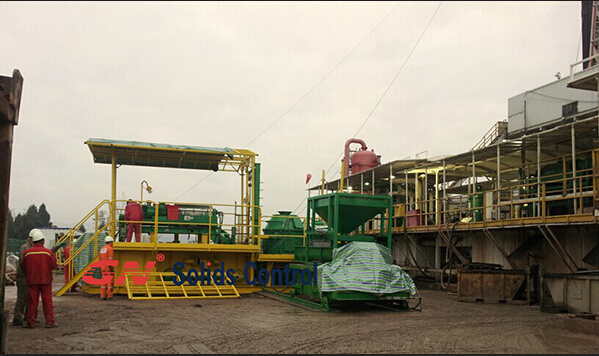
As more and more countries start to control the drilling waste and improve the standard of waste discharge in oil and gas drilling field, drilling waste management becomes more and more popular and important. Many companies have to or want to start their business for drilling waste management. But many clients do not have experience on it. They do not know how to choose the suitable equipment or systems for their activities.
As a worldwide famous brand on mud solids control and drilling waste management, GN Solids Control start its research and development department for drilling waste management and industry waste management for many years. Below is a brief introduction of normal drilling waste management equipment to help the users make decision.
1) High G drying shaker.
It is also named High G dryer, cuttings dryer. It utilizes high G force up to 8.0G to dry the cuttings. If there are big particles in the solids waste, high G shaker is requested. It can remove big size solids and even metal particles. The high G shaker can remove solids above 100 microns.
It is mainly used to treat the water base mud and water based mud cuttings. It can also be used for oil based mud treatment in some cases.
When the high G drying shaker is used to treat oil based mud and cuttings, it can only reduce the oil on cuttings (OOC) to 10 ~ 15%.
It is also called vertical centrifuge or vortex dryer. It utilizes centrifugal force up to 420G to separate the fine solids and recovery the usable drilling fluids. The screen opening of VG dryer is 0.5mm, 0.35mm and 0.25mm. It cannot allow big size sizes solids or metal particles; otherwise, it will be broken.
Vertical cuttings dryer is mainly used for oil base mud and cuttings. It can reduce the oil on cuttings to 3 ~ 5%. In this case, the solids discharge is on a very dry condition and it is easy for shipment. And the solids with 3~5% OOC can be discharged directly in many countries. If not, it is also easy for next treatment.
3) High speed centrifuge and big bowl decanter centrifuge
It utilizes the high centrifugal force to separate the very fine solids to 2~5 microns. It is used after high G shaker and vertical cuttings dryer, for further separation.
There are many other equipment used for drilling waste management, we will introduce in next file.
- Details
-
Published: 25 July 2016